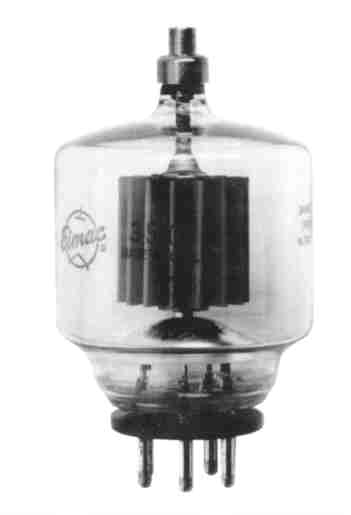
The Elmac 3-500Z is a compact power triode intended to be used as a zero-bias Class AB2 amplifier in audio or radio-frequency applications. Operation with zero grid bias simplifies associated circuitry by eliminating the bias supply. In addition, grounded-grid operation is attractive since power gain as high as twenty times can be obtained with the 3-500Z in a cathode-driven circuit.
From brochure by Eimac, Effective 9/15/91.
Varian
power grid & x-ray tube products
1678 South Pioneer Road / Salt Lake City, Utah 84104 / U.S.A. / (801) 972-5000
| Voltage | 5.0 +/- 0.25 Volts |
| Current @ 5.0 Volts | 14.6 Amperes |
| Amplification Factor(Average) | 130 |
| Cin | 8.3 pF |
| Cout | 0.07pF |
| Cgp | 4.7 pF |
| Cin | 8.3 pF |
| Cout | 4.7 pF |
| Cgp | 0.07pF |
| Frequency of Maximum Rating(CW) | 110 MHz |
2 Capacitance values are for a cold tube as measured in a special shielded fixture
Maximum Overall Dimensions:
| Length | 6.10 in; 154.94 mm |
| Diameter | 3.44 in; 87.33 mm |
| NetWeight | 7oz; 198.5 gm |
| Operating Position | Vertical, base up or down |
| Plate Seals | 225 ° C |
| Base Seals | 200 ° C |
| Cooling | Radiation and ForcedAir |
| Base | 5 Pin Special |
| Recommended Socket | Varian SK-410 |
| Recommended Chimney | VarianSK-406 |
| Plate | HR-6 |
(Frequencies to 110 MHz)
Class AB2
MAXIMUM RATINGS:
| DC PLATE VOLTAGE | 4 000 VOLTS |
| DC PLATECURRENT | 0.4 AMPERE |
| PLATE DISSIPATION | 500 WATTS |
| GRID DISSIPATION | 20 WATTS |
TYPICAL OPERATION
Class AB2, Peak Envelope or Modulation Crest Conditions
| PlateVoltage | 1500 | 2000 | 2500 | 3000 | 3500 | Vdc |
| Cathode Voltage1 | 0 | 0 | 0 | +10 | +15 | Vdc |
| Zero Signal Plate Current2 | 65 | 95 | 130 | 62 | 53 | mAdc |
| Single-Tone Plate Current, CW3 4 | 400 | 400 | 400 | 400 | 400 | mAdc |
| Two-Tone PIate Current | 260 | 270 | 280 | 268 | 262 | mAdc |
| Single-Tone Grid Current2 | 130 | 130 | 120 | 108 | 108 | mAdc |
| Two-Tone Grid Current2 | 80 | 80 | 70 | 60 | 58 | mAdc |
| Single-Tone Power Input | 600 | 800 | 1000 | 1200 | 1400 | W |
| Useful Output Power CW or PEP | 330 | 500 | 600 | 740 | 890 | W |
| Resonant Load Impedance | 1600 | 2750 | 3450 | 4200 | 5000 | |
| Intermodulation Distortion Products5 | ||||||
| 3rd Order | -46 | -38 | -33 | -40 | -40 | db |
| 5th Order | - | - | - | -46 | -45 | db |
| Driving Impedance | 94 | 102 | 100 | 115 | 115 | |
| Maximum Signal Driving Power2 | 49 | 49 | 46 | 46 | 46 | W |
Class AB2 and C Telegraphy or FM
(Key-Down Conditions)
(Frequencies to 110 MHz)
MAXIMUM RATINGS:
| DC PLATE VOLTAGE | 4 000 VOLTS |
| DC PLATECURRENT | 0.35 AMPERE |
| PLATE DISSIPATION | 500 WATTS |
| GRID DISSIPATION | 20 WATTS |
TYPICAL OPERATION
| Grid Driven | Cathode Driven | ||||
|---|---|---|---|---|---|
| PIateVoltage | 3000 | 3500 | 3000 | 3500 | Vdc |
| Grid Voltage | -10 | -75 | -10 | -75 | Vdc |
| Plate Current | 350 | 300 | 333 | 350 | mAdc |
| Grid Current | 115 | 115 | 108 | 118 | mAdc |
| Peak rf (Cathode) (Grid)Voltage | 110 | 187 | 95 | 200 | V |
| Approximate Driving Power | 14 | 22 | 35 | 81 | W |
| Plate Input Power | 1050 | 1050 | 1000 | 1225 | W |
| Plate Dissipation | 330 | 200 | 300 | 305 | W |
| Useful Output Power | 720 | 850 | 700 | 920 | W |
| Resonant Load Impedance | 4200 | 5700 | 4800 | 5500 | ohms |
Class C Telephony (Carrier Conditions)
MAXIMUM RATINGS:
| DC PLATE VOLTAGE | 3 000 VOLTS |
| DC PLATECURRENT | 0.275 AMPERE |
| PLATE DISSIPATION1 | 330 WATTS |
| GRID DISSIPATION2 | 20 WATTS |
TYPICAL OPERATION
(Frequencies to 30 MHz)
| Plate Voltage | 3 000 Vdc |
| Grid Voltage | -100 Vdc |
| Plate Current | 275 mAdc |
| Grid Current1 | 120 mAdc |
| Peak rf Grid Voltage1 | 200 v |
| Calculated Driving Power | 25 W |
| Plate Input Power | 825 W |
| Plate Dissipation | 185 W |
| Plate Output Power | 640 W |
Class AB2, Grid Driven (Sinusoidal Wave)
MAXIMUM RATINGS (Per Tube):
| DC PLATE VOLTAGE1 | 4000 VOLTS |
| DC PLATE CURRENT | 0.4 AMPERE |
| PLATE DISSIPATION | 500 WATTS |
| GRID DISSIPATION | 20 WATTS |
TYPICAL OPERATION (Two Tubes)
| PlateVoltage | 3000 Vdc |
| Grid Voltage | 0 Vdc |
| Zero-Signal Plate Current2 | 300 mAdc |
| Maximum Signal Plate Current | 770 mAdc |
| Max Signal Grid Current2 | 244 mAdc |
| Peak af Grid Voltage3 | 100 V |
| Peak Driving Power4 | 25 W |
| Plate Input Power | 2310 W |
| Maximum Signal Plate Dissipation | 890 W |
| Plate Output Power | 1420 W |
| Load Resistance(plate to plate) | 8600 ohms |
| RF Amplifier | Switching Modulator | ||
|---|---|---|---|
| DC Plate Voltage | 4 | 10 | KILOVOLTS |
| DC Plate Current | 0.4 | 0.4 | AMPERES |
| DC Grid Voltage | -200 | -200 | VOLTS |
| Plate Dissipation | 500 | 500 | WATTS |
| Grid Dissipation | 20 | 20 | WATTS |
TYPICAL OPERATION (Carrier Conditions) | RF Amplifier | Switching Modulator | |
| Plate Voltage | 3.0 | 9.0 | kVdc |
| Plate Current | 250 | 180 | mAdc |
| Grid Voltage | -85 | -120 | Vdc |
| Grid Current2 | 170 | 125 | mAdc |
| Useful PowerOutput2 | 550 | 1500 | W |
| NOTE: | TYPICAL OPERATION data are obtained by calculation from published characteristic curves or actual measurement. Adjustment of the rf grid voltage to obtain the specified plate current at the specified bias and plate voltages is assumed. If this procedure is followed, there will be little variation in output power when the tube is changed, even though there may be some variation in grid current. The grid current which results when the desired plate current is obtained is incidental and varies from tube to tube. These current variations cause no difficulty so long as the circuit maintains the correct voltage in the presence of the variations in current. If grid bias is obtained principally by means of a grid resistor, the resistor must be adjustable to obtain the required bias voltage when the correct rf grid voltage is applied. |
| Min | Max | ||
|---|---|---|---|
| Filament: Current at 5.0 Volts | 13.8 | 15.0 | Amperes |
| Interelectrode Capacitance1 (Grounded Filament Connection) | |||
| Input | 6.5 | 10.0 | pF |
| Output | - | 0.18 | pF |
| Feedback | 4.2 | 5.2 | pF |
| Interelectrode Capacitance1 (Grounded Grid Connection) | |||
| Input | 6.5 | 10.5 | pF |
| Output | 4.2 | 5.2 | pF |
| Feedback | - | 0.18 | pF |
| Zero Signal Plate Current: | |||
| (Ec=0Vdc Eb=Vdc) | 90 | 180 | mAdc |
SOCKET - The EIMAC SK-410 air system socket and the SK-406 chimney are recommended for use with the 3-500Z. When a socket other than the SK-410 is used, provisions must be made for equivalent cooling of the base, the envelope, and the plate lead.
If a socket other than the EIMAC SK-410 Is employed, the user should assure himself that strong lateral pressure is not applied to the tube base pins. Otherwise, even though the base of the tube is reinforced, damage to the base seals may result.
CAUTION-GLASS IMPLOSION - The EIMAC 3-500Z is pumped to a very high vacuum, which is contained by a glass envelope. When handling a glass tube, remember that glass is a relatively fragile material, and accidental breakage can result at any time. Breakage will result in in flying glass fragements, so safety glasses, heavy clothing, and leather gloves are recommended for protection.
COOLING - Forced-air cooling is required to maintain the base seals at a temperature below 200 ° C. Air flow requirements to maintain the above maximum temperatures are tabulated below (For operation below 30 MHz).
| Base-to-Anode Air Flow | ||
|---|---|---|
| Anode Dissipation (Watts) | Air Flow (CFM) | Preassure Drop (inches-H2O) |
| 300 | 6.6 | 0.023 |
| 400 | 10.3 | 0.052 |
| 500 | 13.0 | 0.082 |
The anode of the 3-5002 operates at a visibly red color at its maximum rated dissipation of 500 Watts.
In all cases, air flow rates in excess of the minimum requirements will prolong tube life. NOTE: Two 3-500Z tubes in a single amplifier, chassis mounted, may be adequately cooled by use of a fan so mounted as to pressurize the space below the sockets. Fans suitable for use at or near sea level are Pamotor Model 2000, or Model 6500. The Rotron "Spartan" fan (3200 rpm) is also suitable, as is a #3, 3 inch squirrel cage blower (31 00 rpm) all cases, the only criteria of proper cooling is the temperature of the tube seals Tube temperatures may be measured with the aid of temperature sensitive paint, spray or crayon.
Suitable products are manufactured by the Tempil Division, Big Three lndustrial Gas & Equipment Co., Hamilton Blvd., So Plainfield, New Jersey 07080.
For best tube life, the inrush current to the filament should be limited to two times normal current during turn-on. This will minimize thermal stress on the thoriated-tungsten filament wire, which can cause internal tube geometry changes with repeated cycling.
HIGH VOLTAGE - Operating voltage for this tube can be deadly, so the equipment must be designed properly and operating precautions must be followed. Design equipment so that no one can come in contact with high voltages. All equipment must include safety enclosures for high voltage circuits and terminals, with interlock switches to open the primary circuits of the power supply and to discharge high voltage capacitors whenever access doors are opened. Interlock switches must not be bypassed or "cheated" to allow operation with access doors open. Always remember that HIGH VOLTAGE CAN KILL.
INTERMODULATION DISTORTION - Typical operating conditions with distortion values included are the result of data taken during actual operation at 2 MHz. Intermodulation values listed are those measured at the full peak envelope power noted
INPUT CIRCUIT - When the 3-500Z is operated as a grounded-grid rf amplifier the use of a resonant tank in the cathode circuit is recommended in order to obtain greatest linearity and power output. For best results with a single-ended amplifier it is suggested that the cathode tank circuit operate at a Q of two or more.
SPECIAL APPLICATIONS - If it is desired to operate this tube under conditions different from those given here, write to the Power Grid Tube Marketing Department, Varian, 1678 South Pioneer Road, Salt Lake City, Utah 84104, telephone (801) 972-5000, for information and recommendations.
| DIMENSIONAL DATA | ||||||
|---|---|---|---|---|---|---|
| INCHES | MM | |||||
| DIM. | MIN. | MAX. | REF. | MIN. | MAX. | REF. |
| A | 3.438 | 87.33 | ||||
| B | .350 | .365 | 8.89 | 9.27 | ||
| C | .328 | .359 | 8.33 | 9.12 | ||
| D | 5.200 | 132.1 | ||||
| E | 5.500 | 6.100 | 139.7 | 154.94 | ||
| F | .700 | 17.78 | ||||
| G | ||||||
| H | ||||||
| I | ||||||
| J | 2.500 | 63.5 | ||||
| K | 30 ° | |||||
| L | .185 | .191 | 4.7 | 4.85 | ||
| M | 1.250 | 31.75 | ||||
Click to go home.
Click HERE to study the example design by Eimac on a pair of 3-500Z tubes.
Eimac is available at http://www.eimac.com/.
3-500Z is now produced by Triton Services, Inc of Dunkirk, MD USA. They may be contacted at Triton Electron Technology Division, 3100 Charlotte Avenue, Easton, PA 18042. Phone - 610 252-7331, FAX - 610 258-6279.):
This page has ben scanned and OCR'ed from the Eimac data-sheet. Sincere effort has been given to provide an accurate and correct replication. However, no guaranty is provided for the consequences of any errors on this page, or anyone linked from here. Further, no responsibilities, legal, financial or others will be accepted based on or connected to this page. It has only been provided to the aide of the Radio Amateur Community.